|
|
| |||||
|
|
| |||||
|
| ||||||
High Perfomance Sidecars
BMW K110RS / EML Speed 2000 Ver 2.0
Sway bar Fabrication
There are three major components that make up the sway bar assembly. First the sway bar itself, next the sway bar bushings, and then the end links which connect the sway bar to the bike and sidecar suspension.
The first step was to determine where to run the sway bar, there were many options to consider. Ground clearance had to be taken into account along with the geometry of the bar. Where and how the bar would attach to the bike and sidecar suspension also had to be considered.
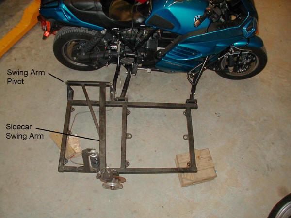
My Speed 2000 has the EML High Comfort Anti-Dive (HCAD) suspension, sort of a side ways mounted swing arm. The pivot is next to the bike and the swing arm runs sideways. This supposedly provides better stability in left-hand corners. (see figure #2)
I wanted the bar to attach to the suspension as far from the pivot as possible on both the bike and the sidecar. This would provide the most leverage to twist the bar as the suspension moves. Next whether to run the bar under the frame, between the frame and the sidecar body, or try to make it fit in the same channel in the body that the swing arm fits into. Then I had to be sure that the bar could move through its range of travel with out hitting the sidecar frame, bike frame, sidecar body, the ground, my right foot, or anything else.
It turned out that the only real option was to run the bar under the sidecar frame. Once this decision was made the next step was to bend the sway bar. I ordered a length of 5/8 inch diameter 4140 alloy steel rod from MetalsDepot.com. A trip to the local Harbor Freight and I had hydraulic pipe bender (it was on sale.) I made a pattern for the bar was made out of some scrap conduit, then the rod was bent to match the pattern. This took a time or two, since the bar would straighten a little when the pressure was released from the pipe bender. I just had to bend a little past where I wanted the bend to be. When necessary I could straighten the bar by wedging it under an immovable object and pulling.
Once the bar was bent I could design and fabricate the mounts for the sway bar bushings. To have better access to the sidecar frame I removed the body from the frame. The sidecar frame is made of 1 ½ inch square tubing, another order from MetalsDepot.com and I had a supply of 1 ½ square tubing to fabricate mounts for the sway bar bushings. Energy Suspension polyurethane 5/8 inch sway bar bushings were ordered from Summit Racing.
For best operation of the sway bar the bushings should be as close as possible to the bends of the sway bar, so that the suspension motion twists the bar and preloads the opposite side suspension. Too much distance between the bend of the sway bar and the bushing and the suspension travel will only bend the end of the bar instead of twisting the bar.
The mount for the sidecar bushing was the easiest to fabricate. I simply ran a piece of square tubing forward from the rear sidecar frame rail to the center cross piece of the sidecar frame and tack welded it in place. Then two bolt holes were drilled to hold the bushing.
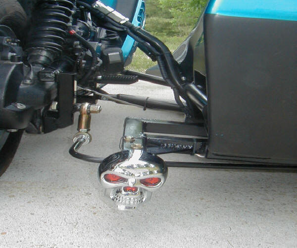
The bike side bushing mount was a little more complicated. Where the bushing should be mounted for best sway bar operation there was nothing but air. An out rigger assembly from the sidecar frame had to be constructed to hold the bushing near the bike. I decided to incorporate a receiver type trailer hitch into the assembly. The outrigger was then tack welded to the frame.
Next to be designed were end links to connect the ends of the sway bar to the bike and sidecar suspension. I chose to use 5/8 inch ball joint rod ends from the McMaster-Carr catalog to connect to the sway bar and the suspension. One female thread rod end and one male thread rod end are used on each end. The rod ends are simply screwed together and secured with a 5/8 jam nut. The length of the end links can be adjusted by how far the rod ends are threaded together. One of the rod ends is to connect to the rig suspension, the other to slide over the ends of the sway bar. The sway bar ends are held in place with clamp on shaft collars placed around the bar on both sides of the rod end. This allows for some misalignment and flex between the suspension and sway bar. Typical car sway bars use a simple rubber bushing between the suspension and sway bar to allow for flex.
Attaching the sway bar end to the sidecar suspension was fairly easy. The sidecar swing arm is made out of 2 inch square tubing. A ¾ inch holes was drilled through the swing arm and a piece of 5/8 inch inside diameter, ¾ inch outside diameter steel tubing was driven through the hole and tack welded into place. A 5/8 inch grade 8 bolt runs through the tubing and through the one ball joint of the end link. (see figure # 3)
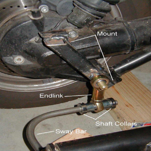
The bike suspension sway bar attachment required fabricating a mount. The mount was made out of 1 ¼ inch square tubing. It attaches to the bike suspension by the stud holding the rear shock to the rear wheel gear housing and the bolt for the rear brake stay arm. Another piece of 5/8 inch inside diameter tubing was driven through a hole in the square tubing and tack welded in place. Another 5/8 inch grade 8 bolt was used to attach the end link to the mount. (see figure # 4)
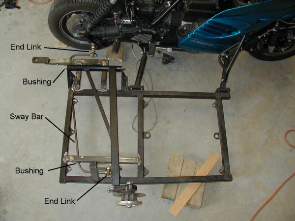
At this point the sway bar was placed in the bushings, everything bolted together, and checked for fit. With the shock absorbers removed the suspension could be moved through its range of travel and the sway bar motion checked to insure nothing was binding or hitting. (see figure # 5) Once everything checked out it was time to disassemble everything for welding, painting, and heat treating.
The sway bar must act as a spring to allow some independent movement of the sidecar wheel and rear wheel. Prior to heat treating it can be easily bent and would add nothing to the handling of the rig. Heat treating the bar turns it into a spring. Not knowing anything about heat treating I talked with Tom Roberts at Carolina Commercial Heat Treating in Reidsville, NC about how best to accomplish this. He hinted at how they heat treated certain parts for NASCAR, I figured if its good enough for NASCAR it should work for me. The sway bar was placed in an oven and baked at 1550 degrees for 2 hours in a protective atmosphere containing carbon. Then the bar was cooled in an oil bath. After this process the bar is extremely hard, but also very brittle. Next the bar was placed in a tempering furnace and the hardness brought down to 45 – 48 Rockwell. (Not all heat treating facilities have ovens large enough to hold a sway bar, it may take some looking to find one.)
As Tom warned me it might, the bar did bend a little when heat treated. Try as I might, there was no way to bend the bar after the heat treating. Luckily there was enough length adjustment in the rod ends to make up for the bending.
While the bar was at the heat treaters the sidecar frame was removed form the bike and all the mount pieces that were initially just tack welded, fully welded in place. This is where the real long term planning comes in. About nine years prior I married a girl whose step father is a welder, so even though I did do a lot of the welding myself, I had someone who knew what they were doing to check my work. Seriously working on suspension components is probably not the time to learn to weld. After all the welding was completed and cleaned up the sidecar frame and sway bar mounts were sprayed with self etching primer and painted.
Once the bar was back from the heat treaters and all the paint dry it was time to bolt everything back together and try it out. Was it worth the time, effort, and cash? Yes, definitely, the rig now corners much flatter than ever before. A few corners that were a little worrisome before the sway bar are now taken much faster than ever. It is a big enough difference that its almost like a new rig, BMW K1100RS / EML Speed 2000 Version 2.0. I was worried that the ride might be to stiff after installing the bar, but it is only slightly noticeable. Installing the sway bar is something I should have done a long time ago.
Now I’ll probably have to install one on the wife’s rig as soon as I finish the back porch renovation project. About the only thing I would do different is to wait until the sway bar returns from being heat treated to drill the holes for the 5/8 inch inside diameter tubing for the attaching the ball joint rod ends to the suspension. That way if the bar warps a little during the heat treating I could adjust the mount locations to compensate. I would go ahead and build the bushing mounts and test fit the bar before heat treating so I could check for interference as the sway bar moves.
While I was there it was time for a new rear tire, so I went with a slightly lower profile and wider tire. Of course it hit the swing arm, requiring a spacer to be made to move the rear wheel a little to the left to clear the arm. As asymmetric as a rig is to begin with didn’t seem that having the rear wheel 3/16 out of line with the front would make much difference. I checked with a few other HPS drivers and found some other rigs with the bike wheels slightly out of line (or maybe it was the drivers out of line, not sure on that.)
The stock exhaust system on my rig is one piece, headers, catalytic converter, and muffler. Taking the rear wheel off my rig required removing the entire exhaust system, a real pain in the a,,aahh,,,,,,,, neck. This seemed like a good time to change to an after market two piece system. So I can remove only the muffler to remove the rear wheel. If it happens to be lighter, sound a little better, be made of titanium, and maybe an extra horse power or two all the better.
In a few weeks I leave for this years gathering of high performance sidecars. Maybe this time I’ll be running with the big dogs.
Now all I need is about 50 more horsepower.
This article is not a cookbook on how to install a sway bar on your rig. It simply discusses my experience adding a sway bar to mine. As mentioned previously, every bike/sidecar combination is different. If you are not sure of your design or fabrication skills get help form some one you trust. Any time you repair or modify the suspension on a vehicle and if that repair or modification fails, there is a chance of serious bodily harm.
Thanks to Ralph Gerkens and Jay Hall for their email advice and comments. Thanks to Bill Ballou for design and fabrication advice and for making the rear wheel spacer. Thanks to Tom Roberts at Carolina Commercial Heat Treating for sharing his knowledge.
Suppliers
| Metals Depot | |
| Rod for sway bar - 4140 Alloy Round, 5/8 inch, 12 foot (they will cut to 8 ft for UPS shipping) | $26.52 |
| bushing mounts – 1½ x 1½ x 14 ga. Carbon Steel Square Tube, 8 ft | $23.04 |
| bike side bar attachment – 1 ¼ x 1 ¼ x 14 ga. Carbon Steel Tube, 4 ft | $9.48 |
| sway bar attachment – ¾ inch O.D. Steel Round Tube, 2 ft | $7.62 |
| McMaster-Carr | |
| Ball Joint Rod End, 5/8 inch, male threaded shank 2 @ $11.10 | $22.20 |
| Ball Joint Rod End, 5/8 inch female threaded shank 2 @ $11.10 | $22.20 |
| Shaft Collars, one piece, clamp on, chrome 4 @ $4.16 | $16.64 |
| Summit Racing | |
| Bushing, Sway Bar Set, Non-grease able, red | $15.69 |
| Carolina Commercial Heat Treating | |
| Heat Treat Sway Bar | $100.00 |
| Local Hardware Store | |
| Stepped drill bit for ¾ inch holes | $25.00 |
| Various nuts, bolts, and washers | $30.00 |
| J.C. Whitney | |
| Receiver Hitch Cover | $24.99 |
| Found in Barn | |
| Paint, Primer, Welding Wire, etc. | |
| Total (does not include shipping) | $325.38 |
|
|
| |||||
|
|
| |||||
|
| ||||||